-
Innovate LM-2 Tacho input fix
Ok, this might be of use to a couple of people at best, but since I'd already written this article for the Innovate forum I thought I'd store it here too.
After struggling for a day with the tacho input on my LM-2 wondering why it refused to work even with a perfect square wave on its input. I did a search on the web and discovered that it's widely accepted that the LM-2's tacho input just doesn't work, at all. It's crap.
People were investing in additional units to interface the RPM signal but I was adamant that I was not going to spend any more money. The LM-2 was not cheap, and really it should be capable of reading something as simple as a tacho signal!!
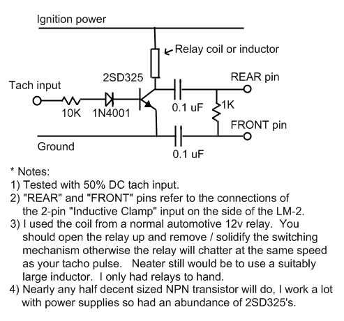
Having given up (like everybody else) on the real tach input I noticed there was an inductive clamp input on the side of the LM-2. I figured the unit probably wanted to see a high voltage spike on that input to signify an HT event, so instead of buying an inductive clamp I knocked up a circuit that converted the normal 50% DC tacho signal (IE the signal from a Renault AEI, or my aftermarket ECU) into something that the LM-2 could read as if an inductive clamp was connected to it.
I thought up this circuit using an old relay as an inductor, capable of creating some back-EMF large enough to trigger the LM-2's inductive clamp input.
I used the coil side of an old 4 pin relay as an inductor because I had nothing else large enough. The following circuit turns the inductor on and off at the same rate as the tach input. Nearly any NPN transistor could be used, I just had a lot of 2SD325 and I thought it should be big enough for the job. The back EMF created by switching the inductor on and off is enough to drive the inductive clamp input on the LM-2 (or mine at least!).
Note: my relay coil measured about 280 Ohms and worked fine with me. I suspect that anything even remotely close will work OK since the LM-2 does not seem fussy about the amount of level on it's input, but if you have a selection of relay's then shoot for that sort of resistance.
It is a crude circuit, I don't claim to be an electronics wizard, so if those of you better qualified than myself would like to improve on the circuit then I will not be offended!
Now I just need to work on conditioning the analogue input's, they're crap too and record a lot of noise.
Regards, Chris.
** Additional note: If your tacho signal is 0-12v (like most) then it might be an idea to use a 3.3v Zener diode installed in the opposite direction to the 1N4001 shown in my diagram. It might help further reduce false triggering since the transistor will only be switched on at approx 4v or more.
Scoff
 Posting Permissions
- You may not post new threads
- You may not post replies
- You may not post attachments
- You may not edit your posts
-
Forum Rules


 Reply With Quote