


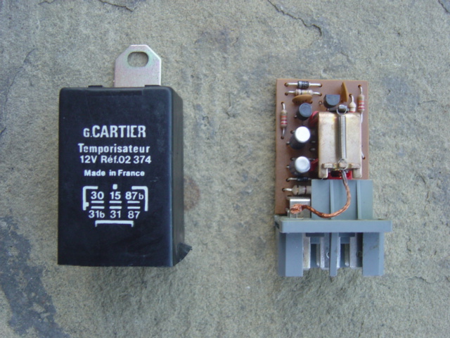
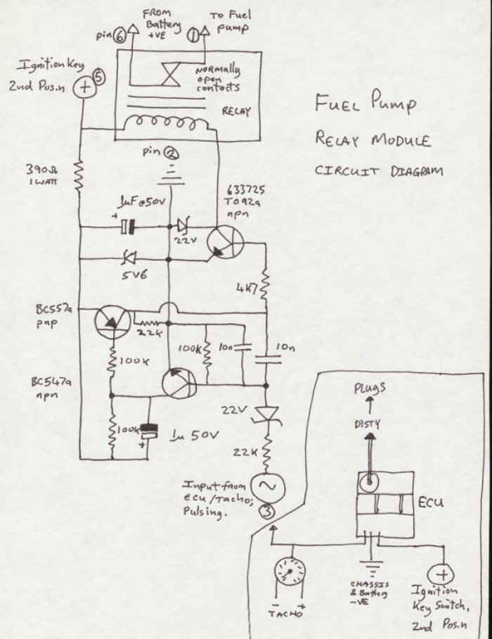
Fuel pump relay module circuit diagram
contributed by Ian Simpson
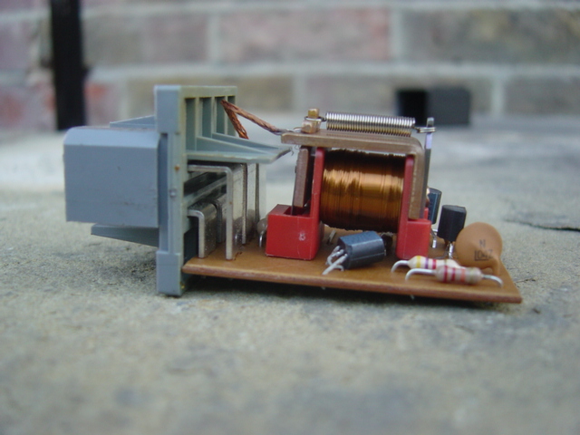
I took the cover off and looked inside...
and after a while drew the schematic.
Please let me know if it's wrong in some way.
A thread
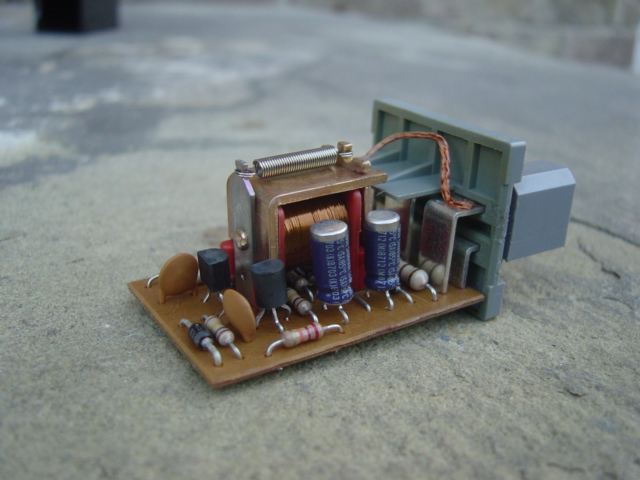
See the second picture down of the module? See the two tall capacitors on the right side. They have been over heated, thats why the plastic sleeving has shrunk back showing the shiny aluminium tops!!! They may well no longer function as capacitors. It is a known fault and they sometimes need to be changed during a repair.
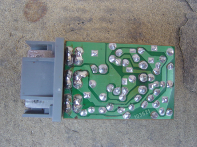
See the fourth picture down. In the middle of the Printed Circuit Board there is some darkening discolouration around one or more of the joints. This is due to the heat produced by the relay coil. These joints can become what is know as Dry Joints. They can look fine but may not actually be conducting electricity so the coil simply doesn't operate. They also can be visibly cracked. This / these joints need to be re-soldered.
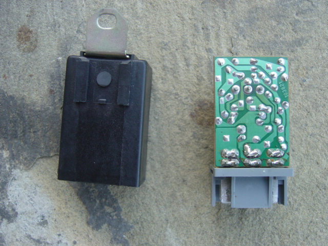
It's also worth looking at the joints where the connector pins join the PCB. These could possibly be cracked due to lack of original solder coupled with vibrational movement over years of use.
Thanks to Bill J for the photos.
Ian S RTOC Profile
Notice the over heated capacitors
See the scorched PCB around the relay coil pad


 Reply With Quote