Results 1 to 27 of 27
  1. #1
    Non-member Matty's Avatar
    Join Date
    Aug 2014
    Location
    Longwick, Bucks
    Posts
    513
    Post Thanks / Like

    EFI inlet manifold

    I have made a fair few EFI manifolds now for other cars, so I have started to make one for the C1J engine, so I thought I would put a build thread on here, to show the progress.

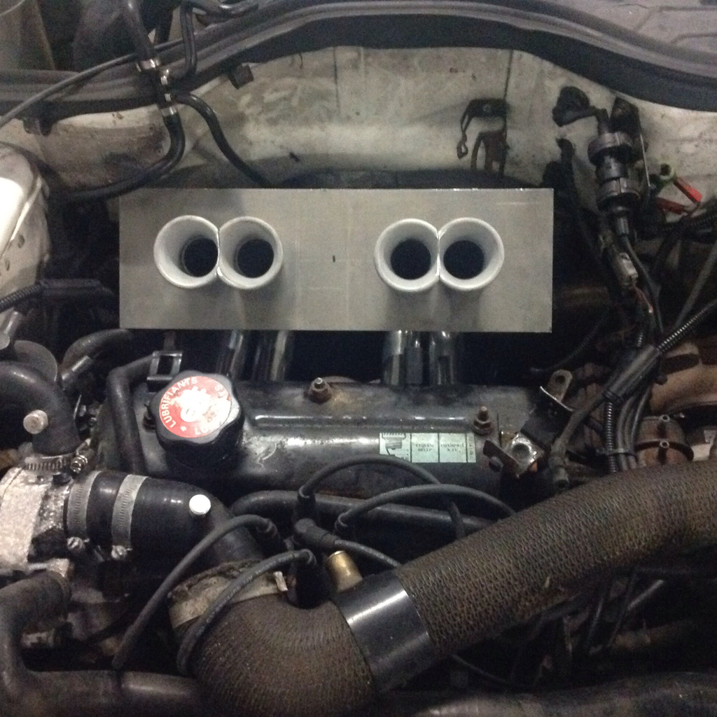
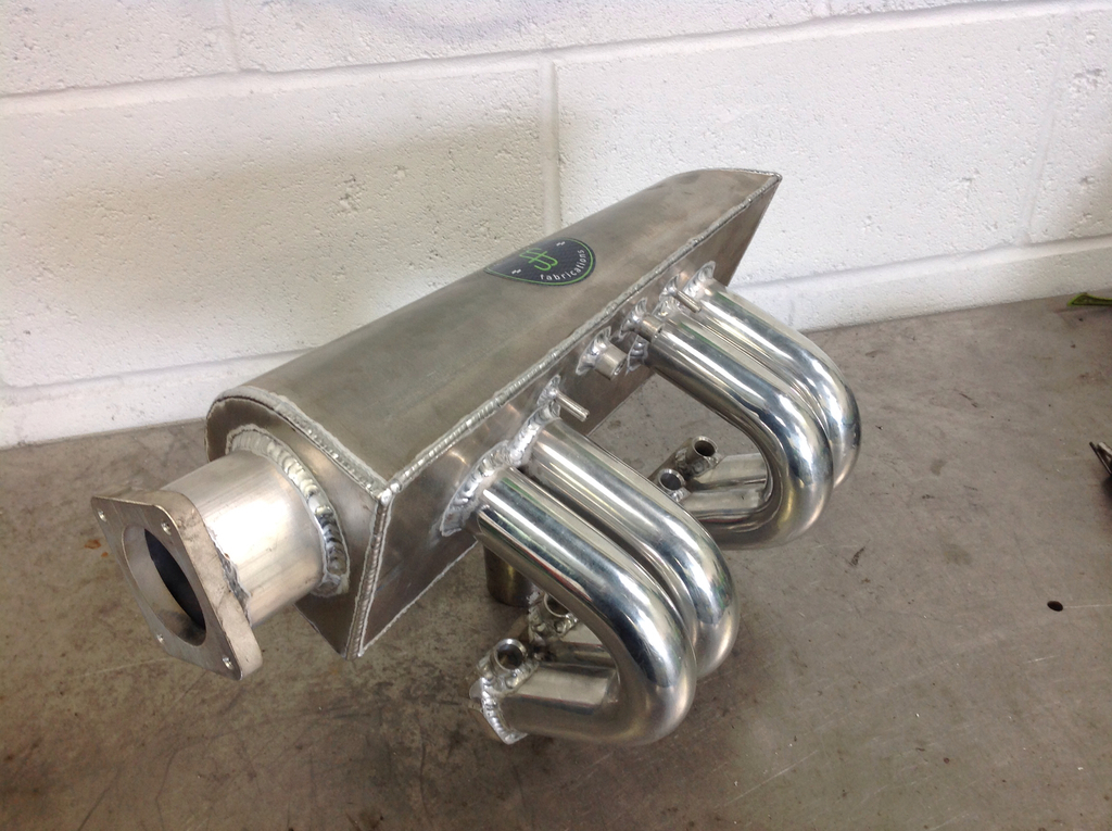
    Following the pattern of the other plenums I have done, this one has matched ports on the inlet flange, internal trumpets inside the plenum to help keep the gas speeds up on low rpm (off boost). The plenum has been sized to give good even distribution of the inlet charge for even mixture accross cylinders, and a tapered housing to also increase air the the furthest cylinders from the TB.

    The throttle body will be a Rover K series, as these are readily available and a good size for the engine, with a good progression on the throttle.


    I was thinking take off wise to have, 1 M8 boss for the brake servo 1 way valve, 1 M12 boss for a standard IAT sensor and a couple of 6mm barbs for the vacuum takeoffs (ecu map sensor, boost gauge etc). Does this sound like enough take offs?

    I have also started making up a swirl pot that fits in the bulkhead compartment that allows the use of the standard low pressure fuel pump. The high pressure pump for the fuel rail can be mounted on the same plate to keep things simple and tidy for the Efi conversion.

    Pics to follow...

  2. #2
    Non-member Matty's Avatar
    Join Date
    Aug 2014
    Location
    Longwick, Bucks
    Posts
    513
    Post Thanks / Like

    Re: EFI inlet manifold

    The basic design mocked up.


    Siamesed trumpets.


    Likes tubbyG liked this post

  3. #3
    Non-member RussellT's Avatar
    Join Date
    Aug 2008
    Location
    Blackpool
    Posts
    786
    Post Thanks / Like

    Re: EFI inlet manifold

    Very interesting, I will be watching this space.
    Likes Matty liked this post

  4. #4
    Non-member tubbyG's Avatar
    Join Date
    Dec 2010
    Posts
    1,074
    Post Thanks / Like

    Re: EFI inlet manifold

    Liking this a lot! This is the sort of design that what would tempt me to go efi for sure

    Do you have an idea where the throttle body will be situated? facing the front of the car, or side mounted?

  5. #5
    Committee, Treasurer, Memberships admin Ian S's Avatar
    Join Date
    Sep 2000
    Location
    Essex
    Posts
    5,832
    Post Thanks / Like

    Re: EFI inlet manifold

    Is joining them in pairs a strength thing? As one would rob the next of air so I would have thought as far apart would be best, with a biggest plenum to smooth out the effect of each intake gulping and lowering the pressure until it fills up again?

    1342. As 2 is at high suction at the bottom of it's stroke (half way down being the highest downward speed of the piston, so max suction?), 1 is on the overlap, an important area it seems, so you don't want the downward moving column or air with high momentum drawing out some of the more static air in the number 1 runner during the overlap. The same for 3 sucking out 4 during it's overlap. That might make a bit less power in 1 and 4.

    Though at least the gas is all going left or right. When 4 is filling and 2 opens, the momentum is all toward 4. And for 1 and 3.

    Would the length of these runners be for a moderate power road car, for higher power you'd choose shorter ones? How long or short would be the tuning part of it.

    Should each runner be a similar volume to the cylinder? 350cc in this case. Then the resistance of the air refilling the runner would buffer the pressure reduction of the plenum and make it easier for the chamber on overlap.

    You can tell I'm not well read on engine tuning or I'd already know all of this!

    I recall reading a bit by Dave Walker in Car and Car Conversion where he was measuring the effect of runner length before the throttles on a straight 4 with ITB's. He seemed to be saying there wasn't a correct length as there was a pulsing effect and that the side of the engine bay was part of the effect of and different lengths just shifted the problem around.

    Different problems perhaps with a single throttle before a plenum and then long runners.

    Would tapered runners help? They'd funnel the air on the way to the port, increasing it's pressure and might give a better chamber fill?

  6. #6
    Non-member Matty's Avatar
    Join Date
    Aug 2014
    Location
    Longwick, Bucks
    Posts
    513
    Post Thanks / Like

    Re: EFI inlet manifold

    Quote Originally Posted by tubbyG View Post
    Liking this a lot! This is the sort of design that what would tempt me to go efi for sure

    Do you have an idea where the throttle body will be situated? facing the front of the car, or side mounted?
    The basic position for the throttle body will be centre of the engine bay (kind of above the turbo). But I can make them to fit where ever. I have found with other previous setups that extending the inlet from the main plenum body to the butterfly does create less responsive throttle response though.

    You can just see the round tank in the scuttle area which is the swirl pot, which makes the conversion very straight forward. Adaptronic seem to have the electronics very well sorted for this conversion, so if I can make it easier for people even better.
    Likes tubbyG liked this post

  7. #7
    Non-member Matty's Avatar
    Join Date
    Aug 2014
    Location
    Longwick, Bucks
    Posts
    513
    Post Thanks / Like

    Re: EFI inlet manifold

    Quote Originally Posted by Ian S View Post
    Is joining them in pairs a strength thing? As one would rob the next of air so I would have thought as far apart would be best, with a biggest plenum to smooth out the effect of each intake gulping and lowering the pressure until it fills up again?

    1342. As 2 is at high suction at the bottom of it's stroke (half way down being the highest downward speed of the piston, so max suction?), 1 is on the overlap, an important area it seems, so you don't want the downward moving column or air with high momentum drawing out some of the more static air in the number 1 runner during the overlap. The same for 3 sucking out 4 during it's overlap. That might make a bit less power in 1 and 4.

    Though at least the gas is all going left or right. When 4 is filling and 2 opens, the momentum is all toward 4. And for 1 and 3.

    Would the length of these runners be for a moderate power road car, for higher power you'd choose shorter ones? How long or short would be the tuning part of it.


    Should each runner be a similar volume to the cylinder? 350cc in this case. Then the resistance of the air refilling the runner would buffer the pressure reduction of the plenum and make it easier for the chamber on overlap.

    You can tell I'm not well read on engine tuning or I'd already know all of this!

    I recall reading a bit by Dave Walker in Car and Car Conversion where he was measuring the effect of runner length before the throttles on a straight 4 with ITB's. He seemed to be saying there wasn't a correct length as there was a pulsing effect and that the side of the engine bay was part of the effect of and different lengths just shifted the problem around.

    Different problems perhaps with a single throttle before a plenum and then long runners.

    Would tapered runners help? They'd funnel the air on the way to the port, increasing it's pressure and might give a better chamber fill?

    On a short runner single Venturi style inlet, charge robbing is an issue as the air doesn't have as much time to change direction and air speed to even out. On a longer runner setup, there is more air in the runner intself to supply the initial 'gulp' of air when the valve initially opens, making the first part of the supply more consistant between runners. So the issues with static and moving air is less apparent. Also with the chamber volume being large enough to supply all 4 cylinders at once, this ensures they all get the same air supply at the same pressure. The tapering of the planums helps speed the airflow up down the end of the plenum where you would expect there to be less air.

    They have been siamesed on the trumpets purely due to the packaging and position of the standard ports, the only other way would be to have them coming off the flanges at an angle, at that would leave some of the trumpets pointing towards the flow and some away.

    The main goal is to have the plenum away from the exhaust manifold (for heat soak reasons) and to get the required plenum volume fitted in. With a setup like this I would expect the off boost low to mid range to be very torquey and not so much top end, but due to these engine not being particularly rev happy on the average motor, not an issue. I'm guessing peak torque to be around what 5500rpm on a 285 cam?

    Tapered runners could help on an NA setup, maybe a little on a turbo but the cost to produce such inlet runners would be crazy!

    Pulse tuning is always a weigh up, as its effectiveness is very much in a short power band, and works very similar to exhaust pulse tuning. On a road car being made to suit many engine specs and driver styles then the length above is ideal. If it was say a hill climber using ratio gears, then something designed for a particualr power band may be worth looking into.

    To me the main advantage of EFI is the ability to closely meter the fueling. On theengines I have built and setup on the Dyno the difference between 11AFR and 12/12.5AFR can be 15-20HP on engine around the 170-180hp mark. On a high boost setup then COPS is also worth looking into, but I am not sure whether the adaptronic has the drivers for this?
    Likes Trevhib liked this post
    Last edited by Matty; 16-12-2016 at 19:57.

  8. #8
    Non-member Matty's Avatar
    Join Date
    Aug 2014
    Location
    Longwick, Bucks
    Posts
    513
    Post Thanks / Like

    Re: EFI inlet manifold

    I basically spent most of today making a drilling jig for the injector bosses, I have managed to get them at a 30 degree angle to the inlet flange, so pointing right towards the valve heads.

  9. #9
    Non-member Fordy's Avatar
    Join Date
    Aug 2010
    Location
    Cambridgeshire
    Posts
    563
    Post Thanks / Like

    Re: EFI inlet manifold

    was going to build my own but you seem to be doing a good job so might start saving for it
    Likes Matty liked this post

  10. #10
    Committee, Treasurer, Memberships admin Ian S's Avatar
    Join Date
    Sep 2000
    Location
    Essex
    Posts
    5,832
    Post Thanks / Like

    Re: EFI inlet manifold

    When you're using high boost as I was, 24psi, then being able to adjust the ignition timing is very helpful in dialling out the detonation. Mine would slightly clack at about 3500rpm or so. That limited the boost I could use overall. A few psi extra was found by retarding the TDC sensor, and timing, a bit. But mappable would have been a lot better as, with the new engine, and a 275 cam, during the early running at lowish RPM I was whizzing past cars at only 8psi. That didn't translate proportionally with going up to three time the boost as at only 12psi it was det'ing quite a bit and I had to move the timing back by at least 4 degrees, by reverting the two wires, I forget just now which, but they gave a further 4° advance, and sliding the TDC sensor, losing a lot of that satisfying low to mid rpm torque.

    IIRC, many of these 1.4's seem to peak torque at nearer 3500rpm.

  11. #11
    Member michael tierney's Avatar
    Join Date
    Sep 2008
    Location
    Dublin/Ireland
    Posts
    942
    Post Thanks / Like

    Re: EFI inlet manifold

    very nice going MATTY.....very similar to my own.....but I've gone for 180deg runners
    I'll post pics soon on this thread......its all about time and space......not an easy engine to make
    an "equal length inlet runner manifold" for........plus the only way to prove these things is
    on the dyno and track!!
    keep up the good work!
    Last edited by michael tierney; 17-12-2016 at 22:32.

  12. #12
    Non-member Matty's Avatar
    Join Date
    Aug 2014
    Location
    Longwick, Bucks
    Posts
    513
    Post Thanks / Like

    Re: EFI inlet manifold

    Quote Originally Posted by michael tierney View Post
    very nice going MATTY.....very similar to my own.....but I've gone for 180deg runners
    I'll post pics soon on this thread......its all about time and space......not an easy engine to make
    an "equal length inlet runner manifold" for........plus the only way to prove these things is
    on the dyno and track!!
    keep up the good work!
    To be honest it is not as bad as some I have done, at least there is some space around them on the 5. One I am working on at the moment is a complete nightmare, it took me 4 hours to get the old original inlet off...the wonders of modern car ay!

    I have the first one going on an engine that is already running EFI so it'll be a good back to back comparison with the one they are running currently.

  13. #13
    Non-member Matty's Avatar
    Join Date
    Aug 2014
    Location
    Longwick, Bucks
    Posts
    513
    Post Thanks / Like

    Re: EFI inlet manifold

    Quote Originally Posted by Ian S View Post
    When you're using high boost as I was, 24psi, then being able to adjust the ignition timing is very helpful in dialling out the detonation. Mine would slightly clack at about 3500rpm or so. That limited the boost I could use overall. A few psi extra was found by retarding the TDC sensor, and timing, a bit. But mappable would have been a lot better as, with the new engine, and a 275 cam, during the early running at lowish RPM I was whizzing past cars at only 8psi. That didn't translate proportionally with going up to three time the boost as at only 12psi it was det'ing quite a bit and I had to move the timing back by at least 4 degrees, by reverting the two wires, I forget just now which, but they gave a further 4° advance, and sliding the TDC sensor, losing a lot of that satisfying low to mid rpm torque.

    IIRC, many of these 1.4's seem to peak torque at nearer 3500rpm.
    In my opinion mapable ignition is a must as that effects the mixture as well as the fuelling map. Being able to advance the igntion right up on cruise areas off boost helps make it drive much better too, and boost a little earlier also!

  14. #14
    Committee, Moderator Matt Cole's Avatar
    Join Date
    Sep 2008
    Location
    Durham
    Posts
    5,259
    Post Thanks / Like

    Re: EFI inlet manifold

    Looks excellent this. keep us informed!

  15. #15
    Non-member Matty's Avatar
    Join Date
    Aug 2014
    Location
    Longwick, Bucks
    Posts
    513
    Post Thanks / Like

    Re: EFI inlet manifold

    Some more done today, injector bosses mounted, a brake servo take off, IAT mount and 2 vacuum take offs mounted on. So just some end caps to make and weld on, and a TB flange, and general finishing off on the head flanges. Then just the Fuel rail and mounts to make. (Still waiting for my inverter to arrive to get the my mill working to do this though).

    Pics to follow.


    Likes tubbyG liked this post
    Last edited by Matty; 20-12-2016 at 20:03.

  16. #16
    Non-member Matty's Avatar
    Join Date
    Aug 2014
    Location
    Longwick, Bucks
    Posts
    513
    Post Thanks / Like

    Re: EFI inlet manifold

    Plenum is now done, just working on the fuel rail to work with it now.


  17. #17
    Non-member tubbyG's Avatar
    Join Date
    Dec 2010
    Posts
    1,074
    Post Thanks / Like

    Re: EFI inlet manifold

    Lovley

    Is there still enough room/clearance to fit a strut brace?

  18. #18
    Non-member Matty's Avatar
    Join Date
    Aug 2014
    Location
    Longwick, Bucks
    Posts
    513
    Post Thanks / Like

    Re: EFI inlet manifold

    Quote Originally Posted by michael tierney View Post
    Very impressive and its probably very light too!!!
    Matty i like!!

    Thanks, yeah it is fairly light probably 1.5kgs or there abouts.

  19. #19
    Non-member Matty's Avatar
    Join Date
    Aug 2014
    Location
    Longwick, Bucks
    Posts
    513
    Post Thanks / Like

    Re: EFI inlet manifold

    Quote Originally Posted by tubbyG View Post
    Lovley

    Is there still enough room/clearance to fit a strut brace?
    Good question! I'm not too sure, It sits lower than the carb the end of the plenum in the centre of the car may touch.

  20. #20
    Member Woznaldo's Avatar
    Join Date
    Sep 2008
    Location
    Canberra, Australia
    Posts
    1,914
    Post Thanks / Like

    Re: EFI inlet manifold

    Nice work Matty.

  21. #21
    Non-member Matty's Avatar
    Join Date
    Aug 2014
    Location
    Longwick, Bucks
    Posts
    513
    Post Thanks / Like

    Re: EFI inlet manifold

    Thanks, I finally managed to sort the fuel rail out. Had a Nightmare trying to get my mill to run on single phase!


    Likes Matt Cole liked this post

  22. #22
    Committee, Moderator Matt Cole's Avatar
    Join Date
    Sep 2008
    Location
    Durham
    Posts
    5,259
    Post Thanks / Like

    Re: EFI inlet manifold

    Really looking forward to see how this performs.

  23. #23
    Non-member Matty's Avatar
    Join Date
    Aug 2014
    Location
    Longwick, Bucks
    Posts
    513
    Post Thanks / Like

    Re: EFI inlet manifold

    Yeah me too, it is going on to an engine already running EFI, so it should be a straight forward swap and a good back to back test too.
    Likes robw, Matt Cole liked this post

  24. #24
    Moderator, Committee Trevhib's Avatar
    Join Date
    Sep 2008
    Location
    Derby
    Posts
    5,829
    Post Thanks / Like

    Re: EFI inlet manifold

    Well, it certainly looks the part.

  25. #25
    Non-member Mad_Mat's Avatar
    Join Date
    Jul 2015
    Posts
    43
    Post Thanks / Like

    Re: EFI inlet manifold

    Superb simple design. Hopefully it will work well. Please let us know how it goes. Cheers MM

  26. #26
    Ireland Area Rep turbo ted's Avatar
    Join Date
    Sep 2008
    Location
    Ireland Co. Kilkenny
    Posts
    645
    Post Thanks / Like

    Re: EFI inlet manifold

    Looks spot on the only issue I would fit the throttle body on the other side as you will be heating the air off the turbo
    After its gone through the intercooler it all about performance and ever bit counts with the c1j 😜

  27. #27
    Non-member Matty's Avatar
    Join Date
    Aug 2014
    Location
    Longwick, Bucks
    Posts
    513
    Post Thanks / Like

    Re: EFI inlet manifold

    Thanks, it can be made with the TB either way, This way there is a bit more room for pipework.

    I have already had someone requesting one the other way around, will add some pics of it fitted.
    Likes turbo ted, Matt Cole liked this post

Posting Permissions

  • You may not post new threads
  • You may not post replies
  • You may not post attachments
  • You may not edit your posts
  •