Yes they are different matey. Exhaust is a similar pattern though.
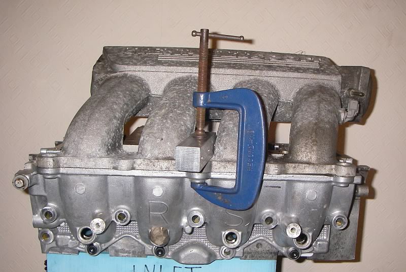
With reference to what Andy is doing, i really need to find out how cack the existing 225 inlet plenum is? It's of a small bore, but not far dissimilar in diameter to the original boost circuit and turbo outlet. Is it worse that the 172/182 inlet? I'm thinking of making up a new inlet manifold if proven there could be of a good benefit. I propose keeping to the same formula as existing but enlarging from 40mm to say 60mm ie an increase in volume. I haven't really looked into the calculations needed to make the manifold work optimum for this engine so some info would be greatly received.


 Reply With Quote