Page 1 of 2 12 LastLast
Results 1 to 50 of 59
  1. #1
    Non-member Andrew Cooke's Avatar
    Join Date
    Sep 2008
    Location
    Oxfordshire
    Posts
    3,160
    Post Thanks / Like

    How not to build a flow bench...

    Meet Henry


    he's looking very smug. I've left him alone with the internet and he's been reading all about fluid dynamics, flow benches, cylinder heads, and all sorts of stuff. I have to keep him in the cupboard, because, quite frankly, he's a bit of a bore. Still, he's handy to have around because I have no idea about any of that stuff, and one of us has to understand what I'm trying to do...

    Anyway, Henry told me I was pissing in the wind poking my fingers inside cylinder head ports and measuring stuff with verniers, what I needed was an Arc, errm, I mean plenum He gets a bit carried away sometimes

    As luck would have it I came across a bit of worktop in a skip at work, with a thumbs up from Henry I slipped it into the Twingo and brought it home.

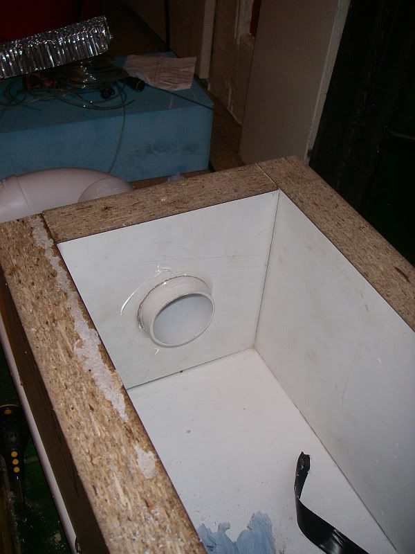
    He told me I needed to build it 300 cubits long, 50 cubits wide, and 30 cubits high. I have no idea how big a cubit is, so I ignored him and built it with internal dimensions of 17cm x 17cm x 34cm.


    why 17x17? that's how deep the throat is on my bandsaw is. Why 34cm long? That gives it about a 10L volume. Why a 10L volume? I don't know, it looked about right

    It's only screwed together at the moment, once it's finished I'll pull it apart and seal all the edges with silicon, apparently it's important to measure the flow through the head rather than how leaky the plenum is....

    So, what next? I have no idea, Henry has taken the hump about the whole cubit thing and is no longer speaking to me.

  2. #2
    Motech Tony Walker's Avatar
    Join Date
    Sep 2005
    Location
    Parkgate Cheshire
    Posts
    3,848
    Post Thanks / Like

    Re: How not to build a flow bench...

    lol, i knew you were going mad when you decided to sell your 5 this just confirms it.

  3. #3
    Non-member Spooky's Avatar
    Join Date
    Sep 2001
    Location
    SW PMT HQ
    Posts
    2,289
    Post Thanks / Like

    Re: How not to build a flow bench...

    nice fire place

  4. #4
    Non-member Matt@CodeRedMotorsports's Avatar
    Join Date
    Sep 2008
    Location
    Kent
    Posts
    2,212
    Post Thanks / Like

    Re: How not to build a flow bench...

    An old back issue of Practical Performance Car had a feature on how to build and test heads with a home made bench, it had David Vizard using it.....might be worth a search for the bits they used to test flow.

  5. #5
    Non-member rs250nut's Avatar
    Join Date
    Oct 2008
    Location
    Learning you can't teach stupid.
    Posts
    2,091
    Post Thanks / Like

    Re: How not to build a flow bench...

    Quote Originally Posted by Spooky View Post
    nice fire place
    X2 wrought iron from the late 1920's early 1930's............... or possibly not

  6. #6
    Non-member Andrew Cooke's Avatar
    Join Date
    Sep 2008
    Location
    Oxfordshire
    Posts
    3,160
    Post Thanks / Like

    Re: How not to build a flow bench...

    Quote Originally Posted by rs250nut View Post
    X2 wrought iron from the late 1920's early 1930's............... or possibly not
    no idea, it was boarded over when I bought the place, either way it's modern compared to the house

  7. #7
    South West Regional Rep jesus in the seat of a 5's Avatar
    Join Date
    Oct 2004
    Location
    Somerset
    Posts
    3,298
    Post Thanks / Like

    Re: How not to build a flow bench...

    Quote Originally Posted by Andrew Cooke View Post
    no idea, it was boarded over when I bought the place, either way it's modern compared to the house
    and the owner.......

  8. #8
    Moderator, Committee Trevhib's Avatar
    Join Date
    Sep 2008
    Location
    Derby
    Posts
    5,829
    Post Thanks / Like

    Re: How not to build a flow bench...

    Cracking thread


  9. #9
    Non-member RussellT's Avatar
    Join Date
    Aug 2008
    Location
    Blackpool
    Posts
    786
    Post Thanks / Like

    Re: How not to build a flow bench...

    Id loose my gonads if I bought that into the house

    I will see if I can find that issue of PPC.

  10. #10
    Non-member TrixNFlix's Avatar
    Join Date
    Oct 2008
    Location
    Preston
    Posts
    2,028
    Post Thanks / Like

    Re: How not to build a flow bench...

    Are you making something similar to this Andrew?
    http://www.tonydrews.com/Flowbench/FlowBench.htm

  11. #11
    Non-member Andrew Cooke's Avatar
    Join Date
    Sep 2008
    Location
    Oxfordshire
    Posts
    3,160
    Post Thanks / Like

    Re: How not to build a flow bench...

    since the fireplace seems to be the most interesting thing in this thread I thought I'd post a better pic of it


  12. #12
    Non-member Andrew Cooke's Avatar
    Join Date
    Sep 2008
    Location
    Oxfordshire
    Posts
    3,160
    Post Thanks / Like

    Re: How not to build a flow bench...

    anyway, the good news is that I made some swarf for Henry to suck up, and he's come out of his deep funk and started speaking to me again.

    I found a slightly more robust bit of worktop in the skip at work, so used that to make a top for the plenum.

    There is more than one way to measure flow, but Henry suggested I went with measuring the pressure drop across a knife edges orifice, so I turned one up on the lathe.


    This fits inside a 50mm Osma joiner. It's tapered on the inside to give a sharp edge on the leading edge. Until I use the bench I won't really know what size I need. so I took a stab at 27mm, this is slightly smaller than the ID of Henry's pipe, and half the cross section of the port in a 172 head.

    I also made up an adaptor from Henry to the 50mm Osma pipe:


    The flow orifice fits inside a 50mm joiner:


    I still need to add some pressure tappings so that I can measure the pressure drop.

    it all fits onto Henry like this:


    I previously had my Gordini heads checked on a mate's flow bench, I'd made a few bits up to do this, so here they are. The blue block is bored out to 76mm as per the C1J to shroud the valves in a realistic manner.


    The other thing I made was something to open the valves with


    it's not easy to see, but the top is tapped out M6, a bolt is threaded through this, and for each turn of the bolt you open the valve 1mm.

  13. #13
    Non-member MFaulks's Avatar
    Join Date
    Dec 2008
    Location
    London UK
    Posts
    197
    Post Thanks / Like

    Re: How not to build a flow bench...

    Henry has been busy

    what size orifice did you go for Andy? Also have you got space for the flow straighteners in there?

  14. #14
    Non-member Andrew Cooke's Avatar
    Join Date
    Sep 2008
    Location
    Oxfordshire
    Posts
    3,160
    Post Thanks / Like

    Re: How not to build a flow bench...

    Quote Originally Posted by MFaulks View Post
    Henry has been busy

    what size orifice did you go for Andy? Also have you got space for the flow straighteners in there?
    27mm. I'm a bit concerned that it'll put the bore too close to the wall of the tube, we'll see, I might need to make another one in the future. But then I'm not too worried about accuracy, just repeatability.

    Flow straighteners.... I tried to buy drinking straws at the local supermarket but they only had bendy ones. I thought about asking, and I may have struck lucky with an off duty engineer, but more likely I'd have got 'Hair straighteners?, you need Boots for them'. As it was I was recounting this sorry tale to one of the wind tunnel technicians at work and he suggested I used a bit of aluminium honeycomb, and that there was bound to be a bit in a bin somewhere. So I scored a bit of 32mm thick honeycomb; seen to the left of the bench in a couple of the pics.

    Length... it's not assembled yet, I was going to have another read through your pm to work out what I need That was just an offcut of 50mm left over from when I fitted my shower, I've got another metre to play with. Sadly it looks like I might need to buy a couple of 90 deg bends

    I was pleased to find Plasticine in my local post office, aged 3+, so I slipped in on that one. The costs are spiralling

  15. #15
    Non-member Andrew Cooke's Avatar
    Join Date
    Sep 2008
    Location
    Oxfordshire
    Posts
    3,160
    Post Thanks / Like

    Re: How not to build a flow bench...

    Martin - you said in your PM that the straighter should be 5x id back from the orifice, so that's pretty simple, 5x52 = 260mm, but what about the other side of the straightener? I have a 90 at one end, and Henry's adaptor at the other. My gut instinct is to allow ~100mm, what's the real story? I've only got a small house, I don't think the neighbour will want me to run plumbing through his living room.

  16. #16
    Non-member MFaulks's Avatar
    Join Date
    Dec 2008
    Location
    London UK
    Posts
    197
    Post Thanks / Like

    Re: How not to build a flow bench...

    Ha-ha+ plasticine .. did you get fussy with the colours Reminds me I need to get some more

    27mm looks a bit big on your bore, but just test and see, all good fun. What you will find is you may loose working range as you don't actually get dead corner regions, and you will see measurement creep. Just try it That or you could reduce the cone diameter if you have problems i.e. decrease the cone angle, as you will be sensing some dynamic flow in your vac side corner tap. Edit - actually doesn't look too bad, suck and see

    Flow straightener - if your honeycomb is reasonable on mesh size then you can keep it short (that's why straws were great, got mine from the local cash'n'carry), but the length of the straightener is based on inside ID of the individual comb section. So shouldn't be too long and go 3x to make as compact as possible, shorter than this and it won't have significant effect.

    From your Henry hose you need to get some pressure recovery, especially if it just jumps in diameter to your orifice ID. So go 3x orifice ID from the exit of the Henry tube, then a shortish straighten section, then I guess on your dimensions you could go your 100mm then your orifice plate. That should be enough. I think you have reasonable length up-stream of the orifice (cylinder head side) to put a straightener in there anyway if really needed?

    Why do you need a 90 deg bend, can't you go straight into the side of your damper box with an appropriate sealed coupling of some sort? That would work great. If you did that, you may actually get away without needing the up-stream straightener (head side), as long as you don't change ID dimension until you break into your box.

    As you transition into your box I would go sharp edge on the intake of this tube, and come through the side wall into the void by about 1/2 to 3/4" This shears the flow (90 deg to the flow velocity exit from the bottom of your dummy cylinder), lose a little bit of head pressure capability, but the down stream pressure recovery before your orifice plate has always been more stable in my experience, but test and see

    .. running through the wall ... don't forget to plug into his electric as well while you’re at it
    Last edited by MFaulks; 12-09-2010 at 15:22.

  17. #17
    Non-member MFaulks's Avatar
    Join Date
    Dec 2008
    Location
    London UK
    Posts
    197
    Post Thanks / Like

    Re: How not to build a flow bench...

    Nice jig by the way

  18. #18
    Non-member MFaulks's Avatar
    Join Date
    Dec 2008
    Location
    London UK
    Posts
    197
    Post Thanks / Like

    Re: How not to build a flow bench...

    Whilst I think of it ,how are you thinking of setting head pressure - motor speed on the vac, or a simple air bleed off?

  19. #19
    Non-member Andrew Cooke's Avatar
    Join Date
    Sep 2008
    Location
    Oxfordshire
    Posts
    3,160
    Post Thanks / Like

    Re: How not to build a flow bench...

    Quote Originally Posted by MFaulks View Post
    Ha-ha+ plasticine .. did you get fussy with the colours Reminds me I need to get some more

    27mm looks a bit big on your bore, but just test and see, all good fun. What you will find is you may loose working range as you don't actually get dead corner regions, and you will see measurement creep. Just try it That or you could reduce the cone diameter if you have problems i.e. decrease the cone angle, as you will be sensing some dynamic flow in your vac side corner tap. Edit - actually doesn't look too bad, suck and see

    Flow straightener - if your honeycomb is reasonable on mesh size then you can keep it short (that's why straws were great, got mine from the local cash'n'carry), but the length of the straightener is based on inside ID of the individual comb section. So shouldn't be too long and go 3x to make as compact as possible, shorter than this and it won't have significant effect.

    From your Henry hose you need to get some pressure recovery, especially if it just jumps in diameter to your orifice ID. So go 3x orifice ID from the exit of the Henry tube, then a shortish straighten section, then I guess on your dimensions you could go your 100mm then your orifice plate. That should be enough. I think you have reasonable length up-stream of the orifice (cylinder head side) to put a straightener in there anyway if really needed?

    Why do you need a 90 deg bend, can't you go straight into the side of your damper box with an appropriate sealed coupling of some sort? That would work great. If you did that, you may actually get away without needing the up-stream straightener (head side), as long as you don't change ID dimension until you break into your box.

    As you transition into your box I would go sharp edge on the intake of this tube, and come through the side wall into the void by about 1/2 to 3/4" This shears the flow (90 deg to the flow velocity exit from the bottom of your dummy cylinder), lose a little bit of head pressure capability, but the down stream pressure recovery before your orifice plate has always been more stable in my experience, but test and see

    .. running through the wall ... don't forget to plug into his electric as well while you’re at it
    I'd have preferred grey, but I think they only have that in the adult section. I did avoid the pack with the modern extra bright colours, going instead for the cheaper traditional colours

    The honeycomb has holes of about 3mm, so at 32mm thick it's more than up to it.

    I was planning on using it both sides of the orifice, for no better reason than I can.

    The reason for the 90 is to come out of the left, 2x 90 deg bends to get the flow meter across the front of the plenum (probably secured to it). Not because it's ideal, but just to try and keep it compact. I can use a straight pipe out the end, but it just makes it a bit big.

    I'm not planning on setting the head pressure, just measuring it and correcting to, errm, not sure actually, probably whatever my mates calibration plates were done at.

  20. #20
    Non-member MFaulks's Avatar
    Join Date
    Dec 2008
    Location
    London UK
    Posts
    197
    Post Thanks / Like

    Re: How not to build a flow bench...

    Quote Originally Posted by Andrew Cooke View Post

    I'm not planning on setting the head pressure, just measuring it and correcting to, errm, not sure actually, probably whatever my mates calibration plates were done at.
    It will change with valve opening or any other changes you make, you may not always want to be max'ed out. Either use a bleed, or a little more repeatable, find a nice cheap 12- 16A variac on Ebay, think your motor will pull about 6A full tilt. Will also give you 0-120% so you will be able to over-speed it a little Nobody uses them these days as people think inverter too quickly

  21. #21
    Non-member RussellT's Avatar
    Join Date
    Aug 2008
    Location
    Blackpool
    Posts
    786
    Post Thanks / Like

    Re: How not to build a flow bench...

    Re PPC article its in issue 12 which I havnt got. issue 15 refers to it in the start of a series of articles on head porting thats giving me a headache

  22. #22
    Non-member Andrew Cooke's Avatar
    Join Date
    Sep 2008
    Location
    Oxfordshire
    Posts
    3,160
    Post Thanks / Like

    Re: How not to build a flow bench...

    Don't worry Russell, I think I can muddle through without getting further confused by Mr Vizard's musings

    I cut some holes in the plenum during the week, a big one in the top to let the air in from the head, a medium sized one in the side for Henry to suck on, and a teenie weenie one in the corner to measure the pressure in the plenum.

    I also started sticking the bits together and sealing the corners of the plenum.

    First shot shows the small pipe that I've glued into the corner of the plenum to measure it's pressure. This is the one that would normally show the 10" water, or 25", or 28" of depression that the head flow is tested at.


    next is the vac port that Henry will have to suck through


    you can see that I've left it proud as suggested by Martin Faulks. He's given a lot of advice, all of it good and based on his experiences of building flow benches. I've listened carefully to it all, and taken it on board. Naturally I've also ignored a lot of it I'll probably wish I hadn't before too long, but there you go, it's my bench, he already has his own

    next is the plumbing from the plenum to the flow meter, I had to buy a couple of 90s, it'd be better straight, buy the neighbour poo-pooed me running it through his living room. The beginnings of the flow meter is sat on the floor across the front of the plenum, it's about 70cm long, so should be reasonable.


    Next I drilled 3 small holes each side of the flow orifice and glued in some small pipes. The 3 will be joined together, and the difference in pressure from the vac side of the orifice to the plenum side is a measure of flow.


    Finally I sealed and screwed down the lid. The hole in the top is 89mm dia.

  23. #23
    Non-member Andrew Cooke's Avatar
    Join Date
    Sep 2008
    Location
    Oxfordshire
    Posts
    3,160
    Post Thanks / Like

    Re: How not to build a flow bench...

    last bit for tonight, a joiner to t all those pipes around the orifice


    it's not too pretty as I've got my lathe in bits replacing some shonky T bolts in the top slide

    it looks more complicated than it is, the top 4 pipes are all joined by cross drillings as are the bottom 4. I've glued it in place just to keep the pipes together....

  24. #24
    Non-member MFaulks's Avatar
    Join Date
    Dec 2008
    Location
    London UK
    Posts
    197
    Post Thanks / Like

    Re: How not to build a flow bench...

    looking good Andy. Are you dedicating Henry to the cause? Your blue block material looks quite handy stuff, would there per chance be any more available for liberation?

  25. #25
    Non-member Andrew Cooke's Avatar
    Join Date
    Sep 2008
    Location
    Oxfordshire
    Posts
    3,160
    Post Thanks / Like

    Re: How not to build a flow bench...

    Quote Originally Posted by MFaulks View Post
    looking good Andy. Are you dedicating Henry to the cause? Your blue block material looks quite handy stuff, would there per chance be any more available for liberation?
    Henry's not giving up his day job

    I'll keep my eyes open in the skips, it's quite a big bit to find though..

  26. #26
    Non-member Andrew Cooke's Avatar
    Join Date
    Sep 2008
    Location
    Oxfordshire
    Posts
    3,160
    Post Thanks / Like

    Re: How not to build a flow bench...

    I've thrown a few more bits together to get a handle on how well it's going to work.


    I'm using a small analogue to digital converter I bought for measuring cams and some 3psi pressure sensors to measure the 2 pressures I'm interested in.

    I need to tidy a few things up, but so far, so good.

  27. #27
    Non-member Andrew Cooke's Avatar
    Join Date
    Sep 2008
    Location
    Oxfordshire
    Posts
    3,160
    Post Thanks / Like

    Re: How not to build a flow bench...

    Henry's quest for knowledge has led him to the Gordini head, since it's already been set up for a flow bench it's a good choice to have a first play with. Don't read too much into the numbers as I'm still playing.


  28. #28
    Honorary Member THE MASTER's Avatar
    Join Date
    Aug 2008
    Location
    bracknell
    Posts
    867
    Post Thanks / Like

    Re: How not to build a flow bench...


    it's all about team work

  29. #29
    Non-member Andrew Cooke's Avatar
    Join Date
    Sep 2008
    Location
    Oxfordshire
    Posts
    3,160
    Post Thanks / Like

    Re: How not to build a flow bench...

    Having had a play on Sunday I came to 2 conclusions. First, I needed to be more careful finding the initial 1mm lift of the valve, and second that the software that came with my little USB analogue to digital converter was a bit crappy.

    With the first problem I looked at the shape of the flow curve and tweeked the value for lift until it looked more sensible, it looked like I was 0.3mm out.

    For the second problem I decided I needed to write a front end for the USB gizmo. I hate writing software for PCs, I'm pretty rubbish at it, and haven't done any for 12 years. So, last night I installed Visual Basic 2008 Express which you can get for free off the Microsoft site. There are Active X controls and sample code available for the gizmo, OK, they're for VB6, but they are there. I got the example working late last night and could read the analogue voltages off the screen.

    Tonight I've done a bit more playing, I'm now able to see real calibrated pressures, filter them, zero them, and show CFM direct to the screen. It's a bit rough and ready, but it works. I'm sampling each input at 1.8KHz, it's taking a load of samples. The CFM reading isn't totally stable, but it's not bad.

    I've not fitted the flow straighteners yet, so it should improve.

    Anyway, I repeated Sundays test of the Gordini head taking a lot more care of the valve opening. It was so much easier to test the head with CFM shown direct on the screen.

    The results were:

    The dark blue was the test from Sunday, the yellow is after I'd tweaked the lift, and the light blue was tonight's effort. I'm happy with the repeatability Oh, I also tapped the valve opening bolt to allow the valve to open further.

  30. #30
    Non-member Andrew Cooke's Avatar
    Join Date
    Sep 2008
    Location
    Oxfordshire
    Posts
    3,160
    Post Thanks / Like

    Re: How not to build a flow bench...

    and finally for tonight, a standard Gordini inlet compared to a big valve one


    I guess I shouldn't expect it to make much difference, especially as I only open the valve to 10.25mm

  31. #31
    Moderator, Committee Trevhib's Avatar
    Join Date
    Sep 2008
    Location
    Derby
    Posts
    5,829
    Post Thanks / Like

    Re: How not to build a flow bench...

    Andy. I'd just like to say that you're a genius.

  32. #32
    Non-member Andrew Cooke's Avatar
    Join Date
    Sep 2008
    Location
    Oxfordshire
    Posts
    3,160
    Post Thanks / Like

    Re: How not to build a flow bench...

    Quote Originally Posted by Trevhib View Post
    Andy. I'd just like to say that you're a genius.
    lol, thanks, but I'm far from that

  33. #33
    Committee, Moderator Matt Cole's Avatar
    Join Date
    Sep 2008
    Location
    Durham
    Posts
    5,259
    Post Thanks / Like

    Re: How not to build a flow bench...

    Awesome Andy. I guess it would be interesting measuring the f4r head compared to the f4rt if any difference at all?

  34. #34
    Non-member Andrew Cooke's Avatar
    Join Date
    Sep 2008
    Location
    Oxfordshire
    Posts
    3,160
    Post Thanks / Like

    Re: How not to build a flow bench...

    Quote Originally Posted by MATT C Ringworm Tuning View Post
    Awesome Andy. I guess it would be interesting measuring the f4r head compared to the f4rt if any difference at all?
    Yeah, making up the adaptors to fit an F4R head is my next job, I'm interested in testing plenums as a priority. The interesting thing could be 172/182 compared to 197.

  35. #35
    Non-member Andrew Cooke's Avatar
    Join Date
    Sep 2008
    Location
    Oxfordshire
    Posts
    3,160
    Post Thanks / Like

    Re: How not to build a flow bench...

    One final test of the Gordini before I get bored of it...

    This time with the inlet plenum fitted. My plenum has a removable end cap to allow me to fish bits of piston out when it all goes wrong, the first test "open plenum" is with this removed, this is to see whether the intake runners and bell mouth are OK. The second test 'closed plenum' is with this blanked off, and the head sucking through the throttle body.


    no idea whether that's good or not, but it seems reasonable to me.

  36. #36
    Non-member Andrew Cooke's Avatar
    Join Date
    Sep 2008
    Location
    Oxfordshire
    Posts
    3,160
    Post Thanks / Like

    Re: How not to build a flow bench...

    Ok, I think this is my last C series test. It's a near standard GTT head compared to a standard Gordini head.

    again, don't read too much into the absolute numbers, this isn't calibrated against any kind of standard, but what you can say is that the Gordini head flows the same at 6mm of lift as the GTT head at 9mm.

  37. #37
    Non-member Rob@Backyardracing's Avatar
    Join Date
    Mar 2004
    Location
    Salford (manchester)
    Posts
    1,756
    Post Thanks / Like

    Re: How not to build a flow bench...

    what you need on there is a honda head, turn poor henry inside-out

  38. #38
    Non-member Mart's Avatar
    Join Date
    May 1996
    Location
    Pie & mash shop
    Posts
    4,732
    Post Thanks / Like

    Re: How not to build a flow bench...

    Good work, Andy

  39. #39
    Non-member rs250nut's Avatar
    Join Date
    Oct 2008
    Location
    Learning you can't teach stupid.
    Posts
    2,091
    Post Thanks / Like

    Re: How not to build a flow bench...

    Any chance you could test my b16 head when its back from the us?

  40. #40
    Non-member Andrew Cooke's Avatar
    Join Date
    Sep 2008
    Location
    Oxfordshire
    Posts
    3,160
    Post Thanks / Like

    Re: How not to build a flow bench...

    Quote Originally Posted by Rob@Backyardracing View Post
    what you need on there is a honda head, turn poor henry inside-out
    I think the F4R will test him, what size vales does the Honda have?

  41. #41
    Non-member Andrew Cooke's Avatar
    Join Date
    Sep 2008
    Location
    Oxfordshire
    Posts
    3,160
    Post Thanks / Like

    Re: How not to build a flow bench...

    Quote Originally Posted by Mart View Post
    Good work, Andy
    Thanks Mart, the real work can start now

  42. #42
    Non-member Rob@Backyardracing's Avatar
    Join Date
    Mar 2004
    Location
    Salford (manchester)
    Posts
    1,756
    Post Thanks / Like

    Re: How not to build a flow bench...

    33mm/28mm on the B.

    you get the bent valves out that f4r head

  43. #43
    Non-member Andrew Cooke's Avatar
    Join Date
    Sep 2008
    Location
    Oxfordshire
    Posts
    3,160
    Post Thanks / Like

    Re: How not to build a flow bench...

    Quote Originally Posted by rs250nut View Post
    Any chance you could test my b16 head when its back from the us?
    You'd be better getting someone with a calibrated bench to do that, you're not going to learn much as a single test.

    There is a lot of work sorting out the adaptors, I'm about to start doing the F4R ones, not sure how long that will take, hopefully I'll have something by the end of the weekend.

    I expect to spend weeks playing with the F4R head, just trying to understand what's going on. If you really want to play you'd be better off making your own bench, If you have a bit more space water manometers work great, you can make a much simpler version than mine

  44. #44
    Non-member Andrew Cooke's Avatar
    Join Date
    Sep 2008
    Location
    Oxfordshire
    Posts
    3,160
    Post Thanks / Like

    Re: How not to build a flow bench...

    Quote Originally Posted by Rob@Backyardracing View Post
    33mm/28mm on the B.

    you get the bent valves out that f4r head
    lol, will do, I have 4 F4R heads here in various state of disarray, Ant's will be the casting I use, one is on my car, then I have one for measuring cams, and one to play with. I'm going to mix and match so that I have 2 cylinders worth of valves to play with, one in the cam rig, one in the flow bench. Once we're all sorted it's new valves all around - assuming I find enough to convince me to swap heads...

    So the B shouldn't really flow that much different to the F4R. That might be an interesting comparison.................. for someone else to make

  45. #45
    Non-member Rob@Backyardracing's Avatar
    Join Date
    Mar 2004
    Location
    Salford (manchester)
    Posts
    1,756
    Post Thanks / Like

    Re: How not to build a flow bench...

    so will you be porting/flowing a head yourself and testing as you go looking for improvments, or are you simply testing the early head vs the later heads (squarish inlet port vs the smaller oval port head?)

  46. #46
    Non-member Andrew Cooke's Avatar
    Join Date
    Sep 2008
    Location
    Oxfordshire
    Posts
    3,160
    Post Thanks / Like

    Re: How not to build a flow bench...

    Quote Originally Posted by Rob@Backyardracing View Post
    so will you be porting/flowing a head yourself and testing as you go looking for improvments, or are you simply testing the early head vs the later heads (squarish inlet port vs the smaller oval port head?)
    err, well, it goes like this...

    I was just going to play with plenums, standard, RS, then port one out etc. That was until a chap at work convinced me I need to sort the head out too. From that point I figured I might as well try and get a PH1 as it's supposedly the best....

    The problem is I've only sorted out how to test inlets, I need to blow to test exhausts, and Henry refuses point blank to blow

    Anyway, I have 3 heads sat here, and the exhaust ports are different on them all.

    The totally knackered one I got off SP33DY has small rectangular ports. The second one is similar, but tapers out to the oval of the exhaust manifold, and the head I got off Rob has large oval ports....

  47. #47
    Non-member Mart's Avatar
    Join Date
    May 1996
    Location
    Pie & mash shop
    Posts
    4,732
    Post Thanks / Like

    Re: How not to build a flow bench...

    If you want it (again) for testing, I've got that old Evo head if it's of any use/interest/future ref' use?

  48. #48
    Non-member Andrew Cooke's Avatar
    Join Date
    Sep 2008
    Location
    Oxfordshire
    Posts
    3,160
    Post Thanks / Like

    Re: How not to build a flow bench...

    Quote Originally Posted by Mart View Post
    If you want it (again) for testing, I've got that old Evo head if it's of any use/interest/future ref' use?
    Jesus no, it took me long enough to get rid of it last time

  49. #49
    Non-member Rob@Backyardracing's Avatar
    Join Date
    Mar 2004
    Location
    Salford (manchester)
    Posts
    1,756
    Post Thanks / Like

    Re: How not to build a flow bench...

    so are there any part numbers on the heads to identify which head is which? i couldnt seem to find any...


    but then again, i suppose in terms of a stock motor, stock CR etc, either of the heads will make the same hp anyway (within ~5hp) would they? or is it a case of some have better heads, but milder maps or cams, hence still make 166hp or whatever it is

  50. #50
    Non-member
    Join Date
    Jan 2010
    Location
    durham
    Posts
    371
    Post Thanks / Like

    Re: How not to build a flow bench...

    i have a F4RT Head with a cracked port if that will help with any of this development

    Andy

Posting Permissions

  • You may not post new threads
  • You may not post replies
  • You may not post attachments
  • You may not edit your posts
  •